Using the output pins of the Arduino to flash an LED is the “Hello World” program for many microcontrollers. Its simplicity in both hardware and code makes this a great first project for beginners. In this article, we will utilize the Arduino digital pins to turn an LED on and off by writing only a few lines of code.
Materials Needed:
Arduino Uno, Nano, Mega
Arduino IDE (software)
Resistor 220Ω
LED (any color)
Bread Board
Jumper Wires
What is a Digital Pin?
Simply put, a digital pin refers to one of those “prongs” or “holes” on the side of the Arduino.

There are two modes that the pin can find itself in: input or output. Digital pins set to input will read the voltage at the pin, while pins set to output will set the voltage at the pin. Digital pins are used extensively throughout any project you may tackle in the future, so it’s essential to understand how they work and what they can do.
If a digital pin is set as an output, it can have either two states: HIGH or LOW (on or off). If the digital pin is put in the HIGH state, the microcontroller will change the voltage at that pin to the Arduinos voltage HIGH, which in most cases will be 5 volts. The opposite can be said when the digital pin is set to a LOW state: 0 volts would be designated to that pin.
If, however, the digital pin is set as an input, the microcontroller can read the voltage to determine whether the current state of the pin is HIGH or LOW. When I started using Arduino boards, I know one question I had was what determines when the microcontroller considers the pin to be in the HIGH or LOW state. The answer to this question is quite simple. In the case of a 5-volt board (most Arduinos), the range for an input pin being in the LOW state is from [0, 3] volts and a HIGH state of (3, 5] volts. For the rest of this article, we will only be concerned about digital pins in the output state, but I thought I would introduce you to the idea of setting digital pins as inputs.
Programming a Digital Output Pin
Now that we have a basic understanding of the digital pin, how can we control its mode, and how can we control its state when in output mode? We can accomplish all of this with a few methods in the Arduino IDE: pinMode and digitalWrite.
pinMode(Pin, Mode): sets the mode of the pin
Pin: This argument needs an integer value representing the corresponding number designated to the pin. You can think of the specified number as an ID for that pin. To find the number assigned to a pin, look for the number printed next to it.
Mode: This argument needs to be one of three keywords: OUTPUT, INPUT, or INPUT_PULLUP. I think the first two words, OUTPUT, and INPUT, are self-explanatory in terms of what they do. But, to be thorough, OUTPUT sets the digital pin as an output pin while the INPUT keyword sets the digital pin as an input. The last keyword, INPUT_PULLUP, will set the pin as an input but will also internally add a pull-up resistor to that pin. If you’re unsure what a pull-up resistor is, there is no need to worry; we’ll talk more about those once we start working with input pins.
A quick tip: if the printed numbers are not visible for whatever reason, you can look up “Arduino Uno pinout,” and pictures of the Arduino will appear with all the pins labeled.
digitalWrite(Pin, State): changes the state of an output pin
Pin: Again, this argument takes in an integer value representing the corresponding number designated to that pin. The number is printed next to the pin, or you can look up the pinout online.
State: Like the mode argument in the pinMode method, this argument will use one of two keywords: HIGH or LOW. If the keyword HIGH is passed, the pin will be set to the Arduinos voltage HIGH, typically 5 volts. If the keyword LOW is given, the pin will be set to zero volts.
One more method we will need to utilize in this program is the delay method. This method will allow us to pause the program for a given amount of time. We need to do this because the program will execute the code too quickly for our eyes to detect any change in the LEDs state after we use the digitalWrite method.
delay(duration): pauses the program for a set period
Duration: An integer value given in milliseconds. (1000 milliseconds = 1 second)
Creating the Circuit
Now that we have a basic understanding of the methods we will be using to control the digital pins on the Arduino, it’s time to create the circuit. If you see yourself getting confused at any point during this section, you can always look at the completed circuit diagram. For this project, we will be controlling pin 7 on the Arduino; you can use a different digital pin if you like. Take one of your jumper wires and place one end into pin 7 and another into any hole on the breadboard.
Next, take your LED and put the positive end (the longer pin) in the same row that connects pin 7 to the breadboard.
Once you have those components connected, take your 220Ω resistor and place any end of the resistor into the same row where the negative end of the LED is located. The negative end of the LED is the shorter pin.

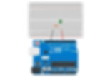
Finally, place a jumper wire in the same row as the end of the resistor that’s not connected to the LED and connect it to a pin on the Arduino labeled “GND.” Your final circuit should look similar to this picture

Writing the Code
Once you have completed your circuit, you can start writing the code to turn pin 7 on and off, blinking the LED. We will use the methods discussed earlier in this article, so be sure to reference those sections if necessary. Below is the code I wrote in the Arduino IDE to blink the LED connected to pin 7.
int LED_PIN = 7;                     //stores the pins assigned number

//this function runs once
void setup() {
  pinMode(LED_PIN, OUTPUT);          //sets the pin as an output
}

//this function runs forever
void loop() {
  digitalWrite(LED_PIN, HIGH);       //Turns the LED on
  delay(1000);                       //Pauses for 1 second
  digitalWrite(LED_PIN, LOW);        //Turns the LED off
  delay(1000);                       //Pauses for 1 second
}
This program aimed to control pin 7 on the Arduino to blink an LED in one-second intervals. The first line of code
int LED_PIN = 7; sets up an integer variable that will store the number assigned to the pin we want to control; in this case, pin 7. After we store the pins number in our LED_PIN variable, the setup function is called and will run only once. In this function, we set the pin mode for pin 7 with
pinMode(LED_PIN, OUTPUT);We set up pin 7 in the setup function because it will only run once at startup (when the Arduino first gets power). It doesn’t make sense for us to constantly set the mode for pin 7 with each iteration of the loop function: you only need to set the mode once. After we set up pin 7, the loop function is called, and this is where we write the code that turns the LED on and off. First, we use the digitalWrite method to turn pin 7’s state to HIGH with this line of code
digitalWrite(LED_PIN, HIGH);Then, we write
delay(1000);to delay the program for 1000 milliseconds or 1 second. Once the delay finishes, we execute another digitalWrite call to put pin 7 in the LOW state, turning the LED off. We follow this command up with another delay of 1000 milliseconds. The overall result of this program is blinking the LED we connected to the Arduino in 1-second intervals. You can change the delays to a longer wait time or shorten them to change the interval. One thing to note is if you make the delay too short, your eye won’t be able to notice the LED blinking. It will appear as if the LED is on permanently. Play around with different delay times and see if you can find a wait time that results in this effect.
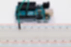
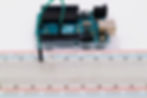
Result
Summary
int LED_PIN = 7;                     //stores the pins assigned number

//this function runs once
void setup() {
  pinMode(LED_PIN, OUTPUT);          //sets the pin as an output
}

//this function runs forever
void loop() {
  digitalWrite(LED_PIN, HIGH);       //Turns the LED on
  delay(1000);                       //Pauses for 1 second
  digitalWrite(LED_PIN, LOW);        //Turns the LED off
  delay(1000);                       //Pauses for 1 second
}
Method | What it does |
pinMode | sets a mode to a pin |
digitalWrite | writes a value, 0 or 1, to a specified pin |
delay | stops the thread for a specified period |